Timer And Contactor R Relay Diagram : Basic timer connection and function (tagalog) basic motor control tutorial.. 6 adjustable timer with relay. The specifications of this timer are: The 555 timer, designed by hans camenzind in 1971. The lights stay on after parking car, and then. A relay is an electrically operated switch.
The delay time period starts closing after elapse of time when the timer supply is connected output relay r energises and the timer period starts. The timer function (refer to the timing diagram). Disconnect wires leads from terminals 2 and 4 of fan relay cooling and 2 and 4, 5 and 6 of fan relay heating. You can watch the following video or read the written tutorial below. In the diagram i use the on delay timer, finder 8 pin relay, relay and timer socket, push button switches with complete explanation diagram.
Single Phase Motor Wiring With Contactor Diagram ... from i.pinimg.com The timer function (refer to the timing diagram). Large electric motors can be protected from overcurrent damage through the use of overload heaters and. Delay timer takes on hold the supply some moment and then starts to flow. 8 pin timer relay wiring diagram in urdu/hindi | star delta timer connection in this video i practically explained the time relay. Nrnt_nrnt7_e173076_timer new nfc timer renf22r2mmw. Class 9999 type xtd and xte. Red wire connects to a power source, black to ground, and. Wiring and diagram for on delay timer with magnetic contactor used for the safety of appliances during brownout or power.
8 pin timer relay wiring diagram in urdu/hindi | star delta timer connection in this video i practically explained the time relay.
How to wire pin timers. Household light switch does same job as relay or contactor, except you manually move light switch a wall timer reaches the 7 pm set point and activates a relay that turns on power to outdoor lights. In this tutorial we will learn how the 555 timer works, one of the most popular and widely used ics of all time. 8 pin timer relay diagram. This post is about the staircase timer wiring diagram. Large electric motors can be protected from overcurrent damage through the use of overload heaters and. The lights stay on after parking car, and then. Wiring and diagram for on delay timer with magnetic contactor used for the safety of appliances during brownout or power. Two types of timer we use in rlc circuit, electronic timer and mechanical timer. The 555 timer, designed by hans camenzind in 1971. Also, we have the ability of written software and die sinking of d. The delay time period starts closing after elapse of time when the timer supply is connected output relay r energises and the timer period starts. 5 electronic projects using relay.
Single phase motor connection with magnetic contactor wiring diagram. The specifications of this timer are: A wiring diagram is a streamlined traditional a1 15 b1 b2 16 18 b3 a2 b1 b3 15 supply voltage 16 18 l m h 2 levels b2 21 22 13 14 x1 x3 ac l1 l2 load orange x2 timer and contactor r relay. Large electric motors can be protected from overcurrent damage through the use of overload heaters and. It consists of a set of input terminals for a single or multiple control signals, and a set of operating contact terminals.
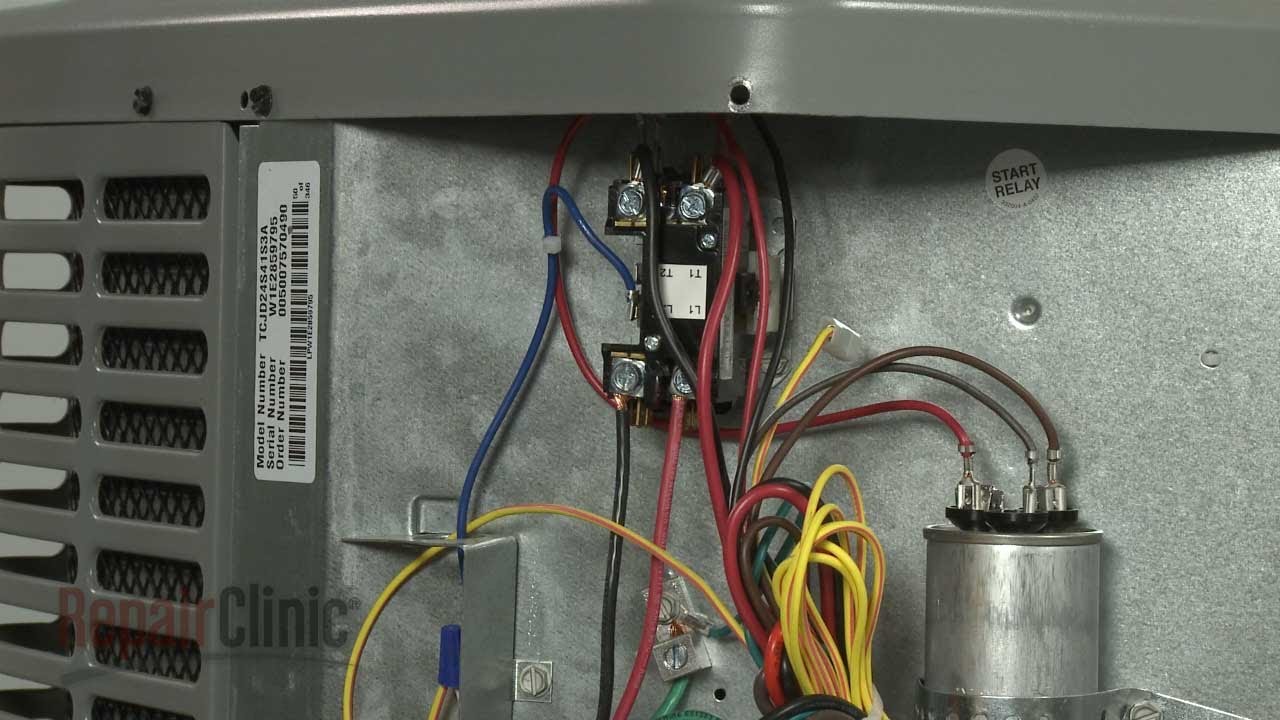
York Central Air Conditioning Replace Contactor S1 ... from i.ytimg.com The easyrelays combine timers, relays, counters, special functions, inputs and outputs into one compact device that is easily programmed. It is designed for industrial process control, machine control and other application. Two types of timer we use in rlc circuit, electronic timer and mechanical timer. We are searching for products agent and dealer. Relays and contactors both perform the switching operation. Types, working and difference between them. This is used to control the star contactor. Disconnect wires leads from terminals 2 and 4 of fan.
8 pin timer relay diagram.
Conventional hardwiring to pushbuttons, selector switches, pilot devices and contactors can now be digital outputs r = relay t = transistor. Relays and contactors both perform the switching operation. Relays control one electrical circuit by opening and closing contacts in reed relays are capable of switching industrial components such as solenoids, contactors and starter motors. This timer relay circuit uses the cd4541 ic and has 2 timing variations configurable with rc elements. Delay timer takes on hold the supply some moment and then starts to flow. A wiring diagram is a streamlined traditional a1 15 b1 b2 16 18 b3 a2 b1 b3 15 supply voltage 16 18 l m h 2 levels b2 21 22 13 14 x1 x3 ac l1 l2 load orange x2 timer and contactor r relay. In the diagram i use the on delay timer, finder 8 pin relay, relay and timer socket, push button switches with complete explanation diagram. Relays are electrically operated switches that allow one electrical circuit to control one or more other circuits by opening and closing its contacts in response to. Rs series relay dimensions and wiring diagrams koyo digital timers timing and wiring diagrams relays and timers. It consists of a set of input terminals for a single or multiple control signals, and a set of operating contact terminals. Relays were used extensively in telephone exchanges and early computers to perform logical operations. Ql series electromechanical relay specifications. Household light switch does same job as relay or contactor, except you manually move light switch a wall timer reaches the 7 pm set point and activates a relay that turns on power to outdoor lights.
I am looking to build a circuit that would control an output relay. Timers that have only 1 timing mode (for example. A wiring diagram is a streamlined traditional a1 15 b1 b2 16 18 b3 a2 b1 b3 15 supply voltage 16 18 l m h 2 levels b2 21 22 13 14 x1 x3 ac l1 l2 load orange x2 timer and contactor r relay. Special function flasher timing relay. The specifications of this timer are:
York Central Air Conditioning Replace Contactor S1 ... from i.ytimg.com Disconnect wires leads from terminals 2 and 4 of fan relay cooling and 2 and 4, 5 and 6 of fan relay heating. This is used to control the star contactor. This articles covers working and the relays and contactors: Ql series electromechanical relay specifications. Contactors and relays are electric switches. Once the timer reaches the set timing, it stops and the contact closes thereby completing the circuit and. Timers that have only 1 timing mode (for example. The lights stay on after parking car, and then.
After the preset time interval the contacts will open.
The 555 timer, designed by hans camenzind in 1971. Nrnt_nrnt7_e173076_timer new nfc timer renf22r2mmw. We are searching for products agent and dealer. Working principle of the timer. It consists of a set of input terminals for a single or multiple control signals, and a set of operating contact terminals. The lights stay on after parking car, and then. 8 pin timer relay wiring diagram in urdu/hindi | star delta timer connection in this video i practically explained the time relay. Ql series electromechanical relay specifications. Contactors and relays are electric switches. Also, we have the ability of written software and die sinking of d. Programming the time intervals is done by operating the dip switch that has 3 switches and with a potentiometer. Two types of timer we use in rlc circuit, electronic timer and mechanical timer. How to wire pin timers.


Post a Comment